
In addition however is a formula which complicates things: √(R^2 + XC^2). The XC formula would be sufficient and I'd be happy to leave it at that. Yes, it would all be simpler if I'd seen only the calculator at the '' webpage (post #2). Impedance is capacitor voltage divided by capacitor current, and then we get 77 Ohm from your experiment. It's not expected when we see that the only variables are Farads and frequency in the XC formula. The upper resistor needs to be 32.3 ohms, which tells us that's the effective impedance of the capacitor. (It appears to be 0.5 multiplied by the square root of 2.)Īt right, the upper resistor was adjusted so output amplitudes match. We expect it should create a twin 77/77 divider. I increased ohmic resistance to 77 ohms, to see ifĬapacitive impedance still indicates 77 ohms according to the raw XC formula. He missed that you specified the proper complex value. I'm sorry you were confused.Ĭhiques, my comment was for BradtheRad and his comment. It was a simple question that nobody could explain clearly. The original question was clear: 50.04 -j77.16
#Smith chart calculator how to#
Why do you confuse people if you don't understand the Smith Chart, and how to read it? Īlright, after reading everyone's input, this is what I get. Respectfully - even if there is loads of resistance as there is here - 50 ohm in fact - the Smith chart tells you the reactive impedance AND the resistive impedance hence 50-j77 ohm. However if the resistor value is increased, it changes the situation so that C needs to be adjusted to a different value. When there is negligible ohmic resistance, it's true that the capacitive reactance formula tells the impedance. He reactive part is 77.16 ohms, this is the sum of the Xc & XL, at 205MHz it is basically all capacitive so yes = Xc The calculation needs to be fine-tuned by drawing parallelogram angles as shown in textbooks.

There is a difference due to a phase change.
#Smith chart calculator series#
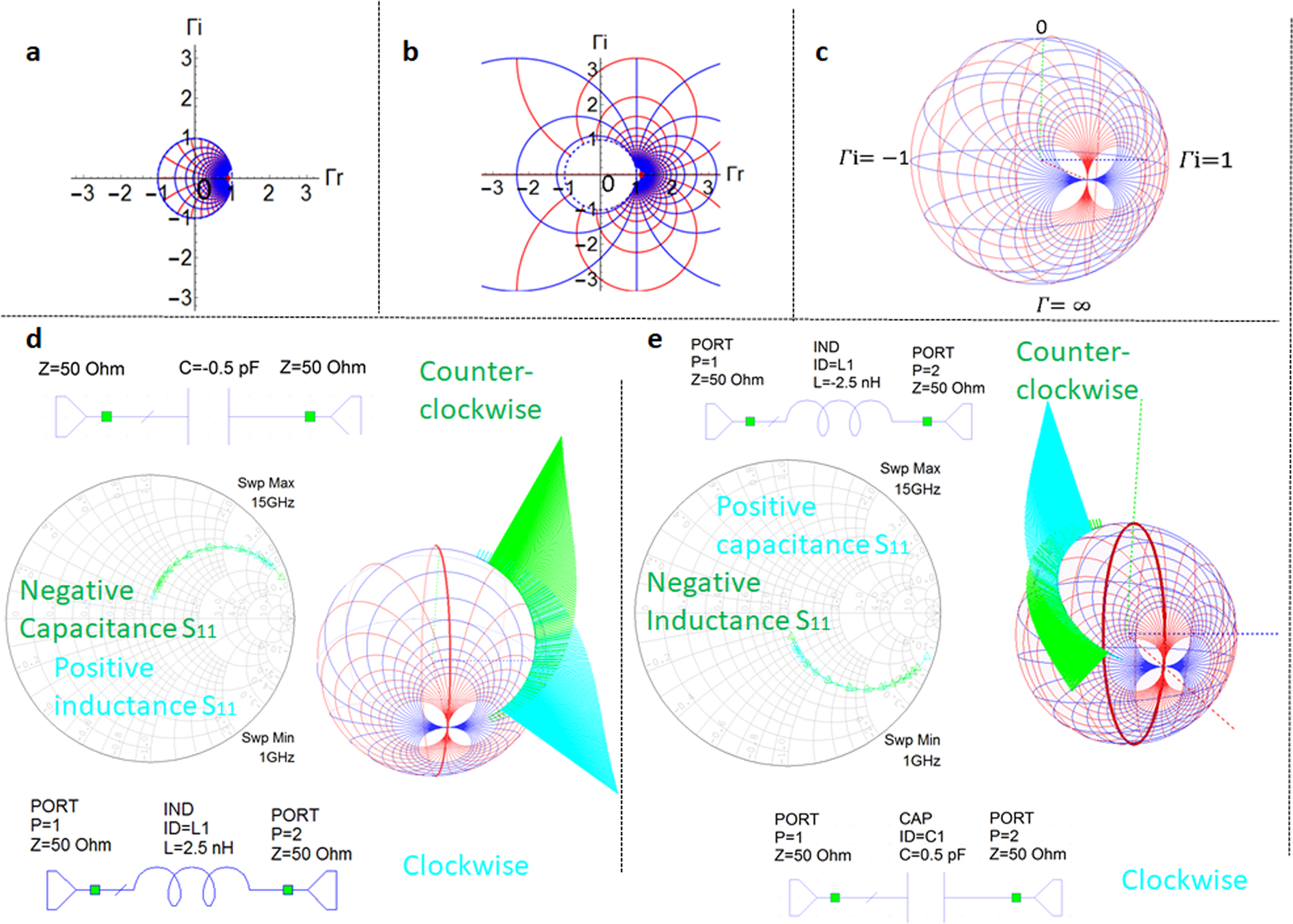
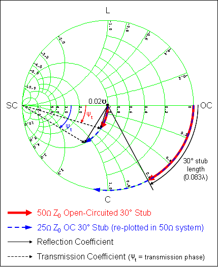
The Smith chart is for a specific 10pF cap, that is clue #1, it is not explicitly shown on the Smith chart, but the 77 ohm at 205MHz gives you 10pF, presumably at very high freq the series L would reduce this figure. Where/How did you see 10pF from the R+jX values on the Smith Chart? (of course I'm assuming the yellow window calculating everything for us is not always there). I see the real part (50Ohm) and the impedance in the imaginary part (77 Ohm).

The smith chart for that cap shows you that at 205MHz it is 10pF ( 77 ohm ) and 50 ohm resistive. So my impedance is 77.16 Ohm? Do I use this as the reactance (Xc)? How do I convert 50.04-j77.16 on a 50 Ohm Smith Chart to a capacitance value of 10.1pF?


 0 kommentar(er)
